| Monolith Constuction Details |
| Counter starter 08 Feb 99. |
 Disclaimer
Send me your comments! I'd love to get some feedback on what others think about the
Monolith. Email me at [email protected]
|
|
|
| Building The Mononith |

| Monolith Enclosure |
|---|
| Description | Measurment | Quantity |
|---|---|---|
| Top/Bottom | 20 x 20" | 2 |
| Sides | 18 x 26" | 2 |
| Front/Back | 20 x 26" | 2 |
| Parapix Housing |
|---|
| Description | Measurment | Quantity |
|---|---|---|
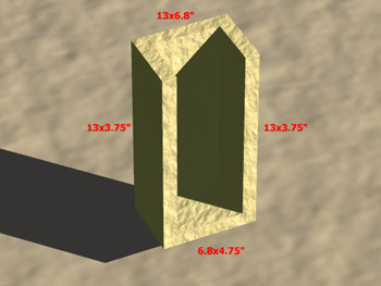
| Sides | 13 x 3.75" | 2 |
| Back | 13 x 6.8" | 1 |
| Top | 4.75 x 6.8" | 1 |
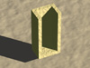
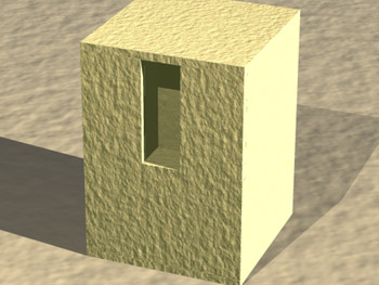
The first thing to build is the housing for the Paramount Pictures Subwoofer amplifier. Using the four pieces cut earlier, assemble the housing as depicted by the following CG Image 1. The measurments in the CG Image are to indicate the piece of MDF, not actual box measurements. Actual box measurments are (LxWxH) 6.8 x 4.75 x 14".
Before we start building the Monolith, we must reconize that not all people will want to finish the outside of the enclosure. If you do, you will have to wait before you cut the holes for the ports until after the finish is attached, unless you have access to some very reliable and accurate tools. However, the driver hole should be cut now.
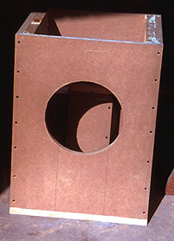
The hole for the SWAN 305 driver is going to be located just below the middle of the Monolith enclosure. Driver placement does not have to be exact, but I used a center position of 11.5" from the bottom of the 20x26" sheet. Find the center width (10") and measure up 11.5" from the bottom. I just traced the hole from the box the driver came in.
With regards to the ports, it would be to hard to perfectly align three holes (2 ports, 1 driver)cut into 2 different layers (MDF and pine finish). Wait until the pine is glued on, then cut the port holes. This is risky, you only have the one chance to do it right. If you can, use a hole saw that is used to cut holes for PVC pipe. I used a jig saw without any trouble. If you are not putting on a finish, you should cut the port and LED holes now. Advance to the ports and LED description. If you are finishing the outside, the ports and LED hole will be cut later.
For the Monolith box, start with one 20 x 20" (top or Bottom) and the 20 x 26"
you cut the driver hole in. 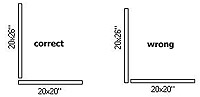 Lay the
20x20" flat and attach the 20x26" to the 20x20" so that the 20x26" sits on
top of the 20x20". Note that the driver hole in the front piece is not directly in the center,
but is closer to the botom. Rotate the front so that driver hole is farthest away from the bottom sheet.
This is because the bottom is actually going to end up being the top when the Monolith is complete. Later, the
ParaPix enclosure will be mounted on the present bottom, and the orientation
of the front/back must be that the fronts driver is low, and the backs ParaPix is high.
The screws should be spaced about 3 inches apart. Next, Attach a side
(18x26") to secure the bottom and the front. View the CG layout
for a clearer picture. Attach the other side so that now only the back and top
are open.
Lay the
20x20" flat and attach the 20x26" to the 20x20" so that the 20x26" sits on
top of the 20x20". Note that the driver hole in the front piece is not directly in the center,
but is closer to the botom. Rotate the front so that driver hole is farthest away from the bottom sheet.
This is because the bottom is actually going to end up being the top when the Monolith is complete. Later, the
ParaPix enclosure will be mounted on the present bottom, and the orientation
of the front/back must be that the fronts driver is low, and the backs ParaPix is high.
The screws should be spaced about 3 inches apart. Next, Attach a side
(18x26") to secure the bottom and the front. View the CG layout
for a clearer picture. Attach the other side so that now only the back and top
are open.
Now we must secure the Parapix box to the bottom (actually the top). Turn the partially completed
Monolith box on its side so that the front is facing up and the exposed back
is on the bottom. Slide the 2nd 20x26" (back) into place but do not fasten it.
Get in a position so that you are looking down into the box through the opening
where the top should be. Clamp the back into place to make sure it does not
move (do not screw it!). Now, slide the Parapix box into position (bottom
center) so that the Monolith's walls complete the walls of the Parapix box.
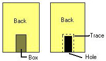 Hold it in tight and
trace its outline with a sharp pencil on all sides. The traced outline
on the Monolith's back will be cut out to allow the insertion of the amp, and
the outline on the bottom will serve as a guide when securing the Ppix box to
the Monolith. Before you cut out the section from the back, remember that you must
measure in 1" from the trace, or the hole will be 1" to big on all sides. If it
were possible, you would have wanted to trace from inside the Parapix box, not
the outside. Do not cut the hole until the Parapix box is attached to the
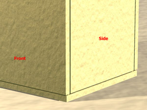
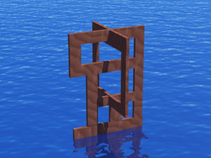
bottom. This way, it is easier to correct any missalignments.View the
CG Image 2 of theParapix box attached to the Monolith,
with the side removed for visibility. Reproduce to trace on the
bottom piece of MDF to its other side (the actual bottom that rests on the
floor). With the Partially completed Monolith box still on its side, the
back still temporaily in position, and Parapix outline on both sides of
the bottom, put the Parapix box in place and have a friend hold it there
firmly so you can drill your holes (2 for each of three sides...6 in
total) from the very bottom, using the trace as a guide. Glue and screw it
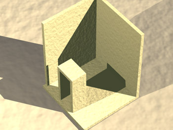
in place. Now stand it up and you should have a view from the behind that
looks like CG Image 3. Note that there is a 1"
space for the back piece of MDF.
Hold it in tight and
trace its outline with a sharp pencil on all sides. The traced outline
on the Monolith's back will be cut out to allow the insertion of the amp, and
the outline on the bottom will serve as a guide when securing the Ppix box to
the Monolith. Before you cut out the section from the back, remember that you must
measure in 1" from the trace, or the hole will be 1" to big on all sides. If it
were possible, you would have wanted to trace from inside the Parapix box, not
the outside. Do not cut the hole until the Parapix box is attached to the
bottom. This way, it is easier to correct any missalignments.View the
CG Image 2 of theParapix box attached to the Monolith,
with the side removed for visibility. Reproduce to trace on the
bottom piece of MDF to its other side (the actual bottom that rests on the
floor). With the Partially completed Monolith box still on its side, the
back still temporaily in position, and Parapix outline on both sides of
the bottom, put the Parapix box in place and have a friend hold it there
firmly so you can drill your holes (2 for each of three sides...6 in
total) from the very bottom, using the trace as a guide. Glue and screw it
in place. Now stand it up and you should have a view from the behind that
looks like CG Image 3. Note that there is a 1"
space for the back piece of MDF.
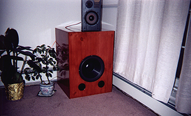
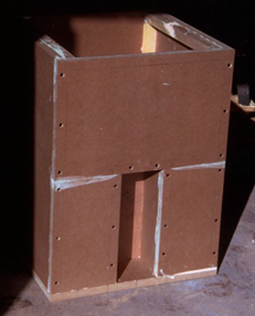
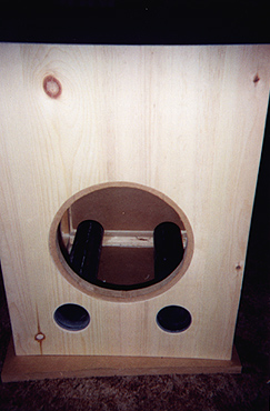
The back piece of MDF can now be cut, after it is confirmed that the original trace is still valid. If so, remove the rectangle. Now you can put it in place, drill the holes, counter sink, glue and screw. Don't forget to screw up from the bottom, as well as into the Parapix box. Screwing into the Parapix box serves a double purpose. First, It does the obvious of tightening the seal between the amp box and the back wall, but it also makes the Parapix Box act as a brace for the back wall. A view from the behind and front of my Monolith. Note: due to poor layout in the original cutting of my 4x8' sheet of MDF, I did not have enough MDF for a 2nd 20x26" sheet, so I had to use three separate pieces.
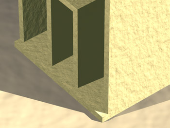
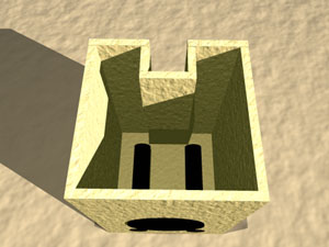
Before the top goes on, the bracing must be put in place. There should be some improvement here upon the present bracing of my Monolith. I will first explain the details of mine, and then how to improve it and why. It is up to you to decide which route to take. When I braced my Monolith, I glued a 1x1" brace along every corner, for the full lenght of the seem. Glue was applied liberally to all sides that made contact to someting (ie another brace or MDF). The problem with this is that there is little to no support for the middle of the walls. It is important to keep the middle's braced to prevent the box from bowing outward (like a ball). This outward expansion will lower the effective output of the Subwoofer. Therefore, I would suggest some sort of "+" brace, in addition to the 1x1" brace, that secures the middle of the walls to the middle of their adjactent walls. View CG Image 4 for an idea of what I mean. You will have to work around the ports, driver and the ParaPix housing. View the CG Image5 of the Pre-bracing Monolith (ports are inserted for the sake of visualization, as with the bottom being removed and the top being secured).
Now, just put the top on and turn it upside down. What we refered to as the bottom was in fact the top. You want the Parapix enclosure near the top so you can access it easily. Also, the ports on the bottom need the open space to ensure proper tunning. View the CG Image 6 of the almost complete Monoltith.
It is now time for the finish. I used 1/4" pine only because it was the least expensive.
It would have been preferable to use a hardwood because pine is soft and dings easy. Pine, from what
I hear stains better though. 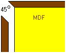 The stain/polyeurathane coating will help stiffin and protect the finish.
Just as you cut your MDF, you will need to do the same except you must add to all sides enough space
so you can mitre the edges (45 degree angle cut). This will hide the edges of the finish. I cannot give
you exact measurments here because my 1/4" pine was not really 1/4". If it were, it would be just a matter
of adding 1/4" to all sides. I did not finish the bottom because it would never be seen.
Once the 5 sides are cut, they are ready to be glued to the Monoliths exterior.
Special care must be taken when gluing the finish on to make sure that it
is attached square. I applied one piece at a time. I first laid down scraps
of MDF and then the finish on top (glue side up). I laid the Monolith on the
finish so its own weight would help disperse the pressure evenly. Make
sure it is aligned right before it settles!!!. If you have lots of clamps,
it would be best to use them...perhaps do all the sides at once using
scraps of wood and long bar clamps to get pressure on the body of the finish
. If you plan to counter sink the driver so that it is level with the
outside of the finish (not resting on top), you can either use a router and
go around the driver hole after the finish is attached (to make a 1/2"
deep or so groove for the driver to drop into), or if you are like me and
do not have the right router bit to do this, you will have to settle for
making the driver hole in the finish only larger before it is glued
on and just have the driver drop a distance of the thickness of the finish
(1/4"). Hope that makes sense. So, if you are using a router (the best way)
, glue the front on now and cut the driver hole later (in the finish...
already cut in MDF) then router. If you do not have a router, take the
piece of finish and put it in place (it would be best to have at least one
side glued on so that the front has something to help keep it aligned) and
clamp it there without glue...remember to use scraps under the clamp feet
so you do not ding your finish!. Drill a pilot hole then cut out the driver
hole to the same size as the one in the MDF. Remove the piece of finish and
drop the driver in. Trace around the driver and then cut this out. Now the
driver should slip through the hole. Once the finish is glued on, the
driver will drop through the finish and hit the MDF. Here is a picture of
my Monolith just before staining. Note the large driver hole in the finish
for the driver to rest in. View pre-stain pic.
The stain/polyeurathane coating will help stiffin and protect the finish.
Just as you cut your MDF, you will need to do the same except you must add to all sides enough space
so you can mitre the edges (45 degree angle cut). This will hide the edges of the finish. I cannot give
you exact measurments here because my 1/4" pine was not really 1/4". If it were, it would be just a matter
of adding 1/4" to all sides. I did not finish the bottom because it would never be seen.
Once the 5 sides are cut, they are ready to be glued to the Monoliths exterior.
Special care must be taken when gluing the finish on to make sure that it
is attached square. I applied one piece at a time. I first laid down scraps
of MDF and then the finish on top (glue side up). I laid the Monolith on the
finish so its own weight would help disperse the pressure evenly. Make
sure it is aligned right before it settles!!!. If you have lots of clamps,
it would be best to use them...perhaps do all the sides at once using
scraps of wood and long bar clamps to get pressure on the body of the finish
. If you plan to counter sink the driver so that it is level with the
outside of the finish (not resting on top), you can either use a router and
go around the driver hole after the finish is attached (to make a 1/2"
deep or so groove for the driver to drop into), or if you are like me and
do not have the right router bit to do this, you will have to settle for
making the driver hole in the finish only larger before it is glued
on and just have the driver drop a distance of the thickness of the finish
(1/4"). Hope that makes sense. So, if you are using a router (the best way)
, glue the front on now and cut the driver hole later (in the finish...
already cut in MDF) then router. If you do not have a router, take the
piece of finish and put it in place (it would be best to have at least one
side glued on so that the front has something to help keep it aligned) and
clamp it there without glue...remember to use scraps under the clamp feet
so you do not ding your finish!. Drill a pilot hole then cut out the driver
hole to the same size as the one in the MDF. Remove the piece of finish and
drop the driver in. Trace around the driver and then cut this out. Now the
driver should slip through the hole. Once the finish is glued on, the
driver will drop through the finish and hit the MDF. Here is a picture of
my Monolith just before staining. Note the large driver hole in the finish
for the driver to rest in. View pre-stain pic.
Now we can cut the port holes for the 3" diameter PVC (you may want to use PNR ports from a mail order store like Crutchfield. or MCM Electronics. Each port has to be 14.85" long. The ports are located below the driver hole at 4.8" from the the bottom (the real bottom now that it is turned upside down...er, right side up) and 5.8" from either side. Note: these measurements are from the post-finish Monolith, so when measuring up 4.8" from the bottom of the front, the front now includes the extra 1" from each top/bottom sheet (the front is now 28" high, not 26"). For those who are not putting a finish on, and advanced here, you must not include the 1" for the bottom sheet because it is not attached yet. Thus, just measure up 3.8" and over 5.55" (5.8"-0.25"...finish) from either side. There is no finish on the bottom, which is why it was not considered when measuring up, as it is when measuring from the sides.
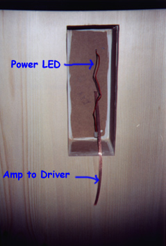
As with the ports, the LED hole should be drilled now if you are not putting a finish on. If you are finishing the outside, drill the hole when you do the ports. The "power on" LED hole is located directly between the ports. I had to extend the LED wire so it would reach from the back to the front. I drilled two holes in the ParaPix housing for the driver and LED wires. I made the holes small enough so they would fit tight in the hole, and then sealed it with hot glue. Here is a pic. The LED has a lip on the bottom that extends around the perimiter of the bulb. I shaved this off to allow the tightest fit in the hole. I forget the exact drill size, but just try a few on a piece of scrap. Once it was in place, I filled the back in with hot glue. Do not glue it in until the finish is stained or the plain MDF is painted etc. It should be the last thing you do before mounting the driver. For those who are not putting a finish on, and advanced to this point, return to the previous section. RETURN
| Performance |
 The Monoliths frequency response curve
is very flat. It's smooth fall off has a -3dB of 25Hz and
a -10dB of 17Hz. Using a sine wave down from 150-20Hz, the Sub would resonate (room
acoustics) at around 50 Hz and 30 Hz. Below 30 Hz made stuff in the kitchen
rattle and vibrate :-) Remember this curve does not account for a +12dB boost at 33.5Hz
that is built into the ParaPix.
The Monoliths frequency response curve
is very flat. It's smooth fall off has a -3dB of 25Hz and
a -10dB of 17Hz. Using a sine wave down from 150-20Hz, the Sub would resonate (room
acoustics) at around 50 Hz and 30 Hz. Below 30 Hz made stuff in the kitchen
rattle and vibrate :-) Remember this curve does not account for a +12dB boost at 33.5Hz
that is built into the ParaPix.
 Again, this reflects the Monoliths flat response curve.
Relatively consistent at 111dB from 35-85 Hz and an appreiciable 108dB at -3dB of 25Hz.
Again, this reflects the Monoliths flat response curve.
Relatively consistent at 111dB from 35-85 Hz and an appreiciable 108dB at -3dB of 25Hz.
 Max SPL of 112dB and max displacement frequency at 20Hz.
Jerry Lynds
Halifax, Nova Scotia
Canada